
TEC Installation
TEC Mounting
There are three methods of mounting thermoelectric modules:
- Compression Method assembly using thermal interface materials such as thermal grease or thermal sheets.
- Adhesive Bonding Method using a thermally conductive adhesive such as epoxy.
- Solder Mounting Method.
A combination of these methods can be used, such as solder mounting the TEC bottom and epoxy mounting the TEC top.
Metallization on the hot and/or cold ceramic faces allows soldering as a means of mounting. Keep in mind a TEC that has no metallization (bare lapped ceramic face) on either side cannot be mounted using solder.
Adhesives and greases are prone to out-gassing, therefore they may not be as appropriate for all applications such as in vacumns and around optical components. Contact us for engineering assistance in selecting outgass safe products.
NOTE: Surface Preparation
Surface preparation is important when using any of the following assembly methods. No matter which method is used, the mounting surface should be flat to less than +/-0.025 mm (+/-0.001 inches) over the TEC mounting area. In addition, the surface should be clean and free from all dirt, oil, scratches and burrs. When multiple TEC's are placed in parallel thermally between two plates, the TEC thicknesses should vary no more than 0.02 mm (0.0008 inches) from lowest to highest points.
Compression Method
Compression assembly is by far the most common method. It is essentially a TEC "compressed" or "sandwiched" between a cold plate and a heat sink (or water block) and maintained in compression by two or more fasteners (screws).
When to Use: When your TEC is larger than 25mm (~ 1 inch), when a permanent bond is not desired; and when multiple TEC's are used.
- Prepare heat sink and cold sink surfaces by machining the module mounting area to a flatness within +/- 0.025 mm (+/- 0.001 inches). Fly cutting or face milling is the preferred method, otherwise machine and then lap.
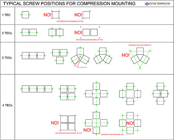
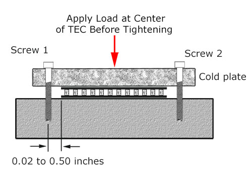
- Locate machine screws in your assembly such that they are at opposite sides of the center of the TEC between 0.5 mm to 12.7 mm (0.02 to 0.5 inches) from the sides of the TEC. The screws should be in the same plane line as the fins to minimize any heat sink bowing (bending) that might occur.
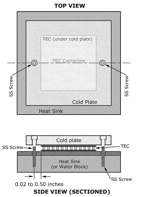
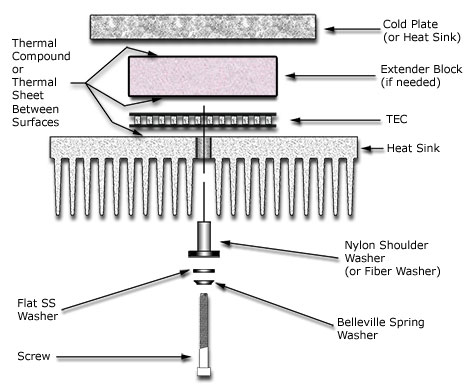
- The recommended hardware is: #4-40, #6-32, or #8-32 stainless steel screws (do NOT use plastic screws as they slowly stretch over time), Belleville spring type washers, flat washers, and insulating Shoulder Washers or fiber washers to thermally isolate the screw from the heat sink. (so the screw is not heated by the hot Heat Sink) An Extender Block (also called a Spacer Block) made of Aluminium or copper may be used to create a greater distance between the cold plate and hot heat sink (or water block) to allow for more insulation. Typical thicknesses of the extender block are 0.25 to 0.75 inches thick and the same width and length as the TEC.
- Remove all burrs. Then, clean and prepare mounting surface with methanol or acetone.
- Thermal Compound or Grease: Apply a thin 0.05 mm (0.002") layer of thermal grease/compound to the hot side of the TEC. Place the TEC on the heat sink (or water block) and rotate back and forth in a clockwise-counterclockwise motion (11 O'clock to 1 O'clock and back and forth), squeezing out the excess thermal grease until resistance is felt. Stop. This is when the two surfaces are now touching with just enough thermal compound to fill the micro gaps.
or
- Thermal Sheet: Cut Thermal Sheet to size with scissors or sharp X-acto knife, just slightly larger than the TEC. Remove protective liner. Pull slowly at 180° angle. Place on intended part and finger rub in place to remove air bubbles. Remove 2nd protective liner. Pull slowly at 180° angle. Bring parts together and continue assembly.
- Repeat step 5 for the other side(s) of the TEC and Extender Block as needed.
- Now determine the torque to apply to the screws. The recommended pressure for TECs is 75 to 200 PSI. Use the following formula and table to determine the Torque in inch-pounds (in-lbs).
 Unified Screw ThreadsMetric ThreadsScrew SizeScrew DiameterScrew SizeScrew Diameter2-560.0864-400.112M2.5 x 0.52.48 (.098”)6-320.138M3 x 0.52.98 (.117”)8-320.164M4 x 0.73.978 (.157”)8-360.164M5 x 0.84.976 (.196”)10-240.190M6 x 1.05.974 (.235”)10-320.190
Example: A single 40x40mm TEC with two # 6-32 machine screws.
Screw diameter = 0.138 inches (from the table above)
Pressure = 125 pounds per square inch (PSI)
TEC surface area » 40mm = 1.575" so 1.575 x 1.575 = 2.481 square inches
So, (0.2) X (0.138) X (125) X (2.481) / (2) = 4.28 in-lbs.
- Now determine the number of Belleville washers needed. First we need to calculate the force per screw in pounds (lbs).
Based on the above example, the total load (force) applied to the TEC by each torqued screw is (125 PSI) X (2.481 square inches) / (2) = 155 pounds
Looking at the Belleville washers listed in our Accessories, we see a # 6 Belleville washer listed as follows;
Part # Description Thick. Working Load ID OD Height FST-BW-06 #6 Stainless Steel Belleville Washer .017 41 lbs. .156 .312 .025 Using the working load of 41 pounds each, then 155 pounds / 41 pounds = 3.78 washers or (rounded up to) 4 washers.
So, each screw will need 4 Belleville washers placed under the head of the screw in the nested (parallel) configuration.
Before tightening the screws, apply a light load/force in line with the center of the TEG by using a clamp or weights. Make sure the clamp or weights apply the force evenly and at the center. Bolt carefully, by applying torque (tightening the screws) in small increments, and alternating between screws. Use a torque limiting screwdriver for best accuracy. Check torque after 1-2 hours and re-tighten as needed. Repeat this check and tightening procedure again after several hours of actual powered use.
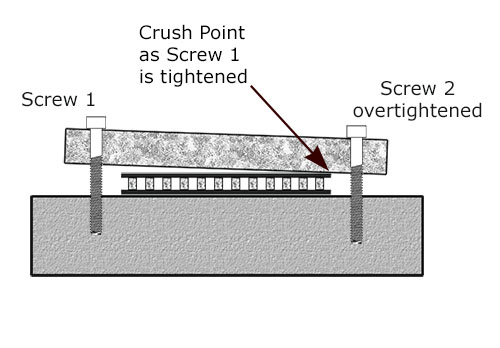
In a two TEC module system, torque the middle screw first. Be careful to apply torque in small increments, alternating between screws. It is of the utmost importance that the screws are tightened evenly in small increments back and forth. If one screw is over-tightened, then the tightening of the second screw may crush the TEC as shown in the picture below.
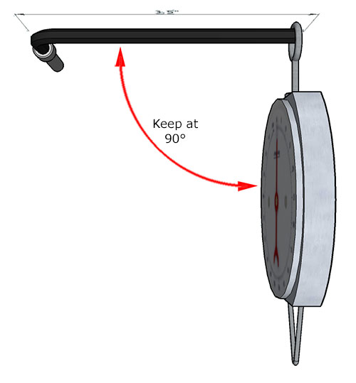
- NOTE: If a torque screwdriver is not available, a reasonably accurate pull spring scale* attached to the end of an L-shaped hex (Allen) wrench (this is a good reason to use socket head cap screws) can be used to determine when the screw torque is reached. Make sure the spring scale is pulled perpendicular (90°) to the Allen (Hex) Wrench at all times.
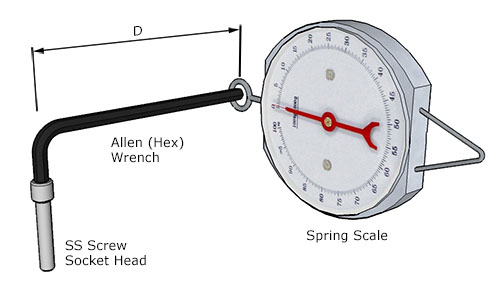
To calculate the required spring scale pull force, use this formula:
F = T / D
F = Force (lbs)
T = Torque (inch-lbs)
D = Distance (inches)Example: What is the spring scale pull force required at the end of a 3.75 inch long L-shaped hex wrench to produce a 24 in-lbs screw torque setting?
F = 24 in-lbs / 3.75 in = 6.4 lbs pull force
[* Test the accuracy of the pull spring scale by hanging a known weight from the scale and adjust as needed]
Adhesive Bonding Method
Typically a thermally conductive adhesive such as epoxy is used to "glue" the TEC to the heat sink or cold plate. An epoxy with a high thermal conductivity is needed to ensure an optimum thermal system. Do Not Use an adhesive when the TEC is larger than 25x25mm.
- Clean both surfaces with acetone 2-3 times with a cotton swab or similar lintless applicator. Use force to reach down into the micro surface scratches and remove any oils and dirt. If possible, use an ultrasonic cleaner (do NOT clean TECs in an ultrasonic) to first clean in a mild detergent, rinse, dry, and then again in acetone. Allow all parts to dry completely. [Once completed, do NOT touch the cleaned surfaces. Oils from the skin will make a low strength epoxy bond and will also decrease the heat transfer.]
- Use Thermally Conductive Epoxy such as Arctic Silver Thermal Adhesive. Follow the instructions on the package carefully. [Be certain to mix the two parts thoroughly or the epoxy will not cure properly. Do not mix the two components ON the TEC or surface to be bonded to. Always mix the two epoxy components on a plastic or metal surface, then apply to the TEC or mounting surfaces. Do NOT mix epoxy on a porous surface such as paper or cardboard as the surface may absorb crucial components of the epoxy compound.]
- Coat the ceramic of the TEC with approximately a 0.05 mm (0.002 inches) thick layer of epoxy. Use a spreader to apply a thin even layer. Make sure all of the ceramic face is coated.
- Place the TEC on the heat sink and apply pressure, squeezing out the excess epoxy. The parts may want to slide or twist out of position, so take care to keep them in place. Optionally, you may wipe away the excess epoxy with the cotton swabs dipped in acetone.
- Using a clamp or weight, apply pressure of 20-50 psi, and cure for 2-4 hours at 60°C to maximize thermal and mechanical properties. Curing time at room temperature is typically 24 hours. Check adhesive packaging for specific instructions.
- Make sure that the TEC that is to be solder mounted is metallized or pre-tinned. If it is pre-tinned, you must know what the melt temperature of the pre-tinning is. If the TEC is not metallized, i.e., it has a ceramic face, you cannot solder mount this TEC. Call customer service for assistance.
- Make sure that the surface that the TEC will be solder mounted to is solderable. This means the surface must be either copper, or copper plated, or pre-tinned. The surface must also be flat to within +/- 0.001 inches (+/- 0.025mm) in the area that the TEC is to be solder mounted to. If the surface is not flat enough, it must be machined, ground, or lapped to this level of flatness.
- Clean the TEC twice with acetone using cotton swabs or other lintless applicator. Use force to reach down into the micro surface scratches and remove any oils and dirt. [Once completed, do NOT touch the cleaned surfaces. Oils from the skin may interfere with the solder wetting process.]
- Clean the surface that the TEC is to be solder mounted to with acetone 2-3 times using cotton swabs or other lintless applicator. Use force to reach down into the micro surface scratches and remove any oils and dirt. If possible, use an ultrasonic cleaner (do NOT clean TECs in an ultrasonic) to first clean in a mild detergent, rinse, dry, and then again in acetone. Allow all parts to dry completely. [Once completed, do NOT touch the cleaned surfaces.]
- Make note of the TEC's maximum temperature, pre-tinning melt temperature (if any), and the melt temperature of the solder you will use to mount with. You must have a hot-plate or other similar device that can be accurately controlled with a temperature setpoint. The main objective is to raise the temperature of the assembly to just above the mounting solder melt point, but stay below the TEC's maximum temperature.
- Lightly and evenly flux the surface and the metallized surface of the TEC with the appropriate flux for the solder you are using.
- (For a pre-tinned TEC or surface) Place the cold plate or heat sink (to be soldered to) on the hot plate previously heated to the appropriate temperature. Place the TEC tinned side down onto the surface and in the correct and desired final position. Allow several minutes for the surface to reach full temperature. As a test, use a small (.125") piece of solder wire as a "witness" by placing it on the surface (but not on the mounting area) and waiting until it melts and beads up. Once the "witness" has melted, you should see that the pre-tinning on the TEC or surface has melted and is being squeezed out on the sides of the TEC. Position TEC correctly and then turn the hot plate off and allow to cool slowly. Do NOT rapidly cool the assembly.
- (Soldering Iron method for tinning non-tinned TEC) With a soldering iron and a new tip, pre-tin the TEC using solder with a melt point below that of the maximum TEC temp. Brighten the metallization on the TEC with 600 grit sandpaper to remove any oxides. Lightly flux with a general purpose Acid Flux. Use small amounts. Melt solder onto the iron tip and then apply iron to TEC and hold. Once you see the solder wet to the TEC, proceed with a swirling motion of the iron tip on the TEC, therby spreading the solder tinning evenly onto the TEC. You can heat the soldering iron to a maximum of 20-30°C above the melt point of the tinning solder, but extreme care must be taken since many TEC's are constructed with 138°C (min.) solder.
CAUTION: Do not mix solders. Use a separate soldering iron tip for each solder. - (For a non-tinned TEC or surface) Place the cold plate or heat sink (to be soldered to) on the hot plate previously heated to the appropriate temperature. Also place the TEC onto the hot plate or surface, but not on the area to be mounted to. Allow several minutes for the surface and TEC to reach full temperature. As a test, use a small (.125") piece of solder wire as a "witness" by placing it on the surface (but not on the mounting area) and waiting until it melts and beads up. Once the "witness" has melted, apply solder to the mounting area to cover the mounting area as evenly as possible without creating a large pool of solder. Using tweezers or pliers, pick up the TEC and place it onto the solder. Molten solder should squeeze out around the sides of the TEC. Position TEC correctly and then turn the hot plate off and allow to cool slowly. Do NOT rapidly cool the assembly.
- After assembly has cooled, wash area with appropriate flux remover.
- There should be a minimum of at least 20°C between melt points used on a single assembly. It is preferred that the "steps" be 40°C to 50°C, but this is not always possible.
- Set hot plates or soldering iron to 20-40°C above the melt point of solder being used, but make sure that this setpoint is still below the melt point of the TEC or other solder melt point used in the assembly.
- Do not allow flux to "burn" or sit too long at an elevated temperature. Timing is crucial. Heat, apply solder, assemble, and cool as quickly as possible.
- If solder, pre-tinning, or copper surface appears tarnished or dull, then it is likely oxidized. Remove oxidation from solder or pre-tinning with a coarse paper towel until it brightens. Remove copper oxidation with a LIGHT buffing with 600 or higher grit sandpaper or very fine steel wool. Re-clean parts as necessary.
NOTE: It is recommended that acetone and cotton swabs be available so any excess adhesive (uncured) may be removed.
Generally, epoxy working time (the time you have to apply the epoxy before it begins to harden) is from a few minutes to several hours. Check package for further information.
CAUTION: Avoid prolonged or repeated breathing of vapor, and use with adequate ventilation. Avoid contact with eyes, skin, or clothing. In case of contact with eyes or skin, flush immediately with plenty of water and seek medical attention.
Solder Mounting Method
Solder mounting has the potential to offer the greatest heat transfer capacity, but can also be the trickiest method of all.
When to Use: When you need minimal out-gassing; when the TEC is smaller than 25 mm; when you need a high-strength junction; when the highest thermal conductivity is required.
Procedure:
General guidelines: