
What TEC do I have?
How to Tell What Kind of Peltier Module You Have
This is a self help guide that attempts to show how you can analyze an unknown Peltier or thermoelectric module to discover its basic specifications. This will allow you to roughly determine equivalent or replacement modules.
The terms Peltier module, Peltier device, Peltier junction, thermoelectric device, thermoelectric module, TEC, TE module, TE cooler are the same and are used interchangeably throughout.
The only sure method of determining what kind of device you have is to send it in to us for a free quick analysis. We will get back to you with all the pertinent data that will allow you to cross reference your old part to a new replacement Peltier device. Working devices are preferred, but if not available, then send the non-working device. Typical turnaround is about a week. Make sure to include all contact information as well as what kind of product the TEC was removed from.
Send devices to:
Custom Thermoelectric
ATTN: TEC Analysis
11941 Industrial Park Road, STE 5
Bishopville, MD 21813 U.S.A.
NOTE: Please include a FedEx or UPS account (or USPS Priority Mail 1 lb postage stamp) if you want the part(s) returned.If you purchase parts from us then we can include your original parts in that shipment.
In Order to replace your part...
You need to know 3 pieces of information in order to find a replacement part for your thermoelectric device. They are;
- Physical dimensions: such as 30 x 30 mm.
- Number of couples in the device: Such as 127 couple (the most common).
- The Imax or maximum amperage rating of the device: Such as 4 amp or 6 amp.
Secondary information needed would be;
- Metallized or lapped faces.
- Sealed or unsealed.
- Length of lead wires and type of insulation.
- Maximum temperature rating of the device.
The steps provided below will help you discover this information.
The Parts:
First, let’s cover the basic parts and components that make up a Peltier cooler device. Look at the pictures below.
The basic components of a thermoelectric device are; two ceramic substrate faces, interconnect pads, the semiconductor pellets (both P and N type), solder to hold it all together, and lead wires. In addition there may be moisture sealant applied to the edge of the device. [Pellets are also commonly called elements, junctions, or dice (dies)]
The ceramic substrates or faces are usually made of Alumina ceramic Al2O3. Less frequently they are made of more thermally conductive ceramics such as Berrylium Oxide BeO or Aluminum Nitride AlN.
Attached to the ceramic substrates are interconnects made of copper. These are either soldered to a metallization on the ceramic or bonded on in a process called Direct Bond Copper (DBC). DBC is the stronger and more superior method of copper interconnect pad attachment.
Soldered to the interconnect pads are the individual semiconductor pellets. There are both N and P type pellets. They are arranged in an alternating pattern, much like a chess board, and form one long series circuit through the entire thermoelectric module.
Markings:
Sometimes, the TECs are marked with a part number that can make your task a lot easier. If you know who the original manufacturer is, then you can simply contact them to find the original specifications. If you have a Cambion thermoelectric device, contact us for a cross reference part.
Many consumer products contain Peltier modules such as wine coolers, electric icechests, mini refrigerators, dorm fridges, cigar humidors, mosquito magnet traps, etc. A vast number of these TECs are manufactured overseas such as in China. Chinese Peltier devices are typically marked with a part number that is common across many manufacturers. A typical example is shown below.
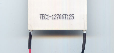
They use the following format; “TEC1-12706 “
The first two letters “TE” are always the same.
Next comes “C” or “S”. “C” denotes a standard device while “S” denotes a “smaller” sizing. This helps when there is more than one possible size such as a 127 couple 4 amp device in both 40mm and 30mm configurations.
Next is a number such as “1”. The “1” after TEC or TES indicates the number of stages in the device – 99% of all TECs are 1 or single stage. A two stage device would obviously have a “2”.
The first three numbers after the dash are the number of Couples, such as “127” or “031”. This can be seen in many product datasheets as "N".
The next two numbers define the Amperage (Imax) of the device, such as “04” or “12”.
Sometimes there is a “T125”, “T150”, or “T200” after the part number that indicates the maximum temperature rating (in Celsius) of the TE module.
Examples;
TEC1-12704 is a 127 couple 4 Amp device
TEC1-03112 is a 31 couple 12 Amp device
TES1-07103 is a 71 couple 3 Amp device in a smaller size than standard
TEC1-12724T125 is a 127 couple 24 amp device rated to 125ºC
Size:
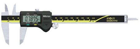
This is the easiest observable specification of a thermoelectric module. Simply measure the length, width, and height of the device as accurately as possible. If possible, use a digital or dial caliper since they are more accurate. Make a notation of the dimensions.
The vast majority of Peltier modules are manufactured in metric dimensions and therefore follow common metric sizing. Typical square sizes (length x width) are 15mm, 20mm, 25mm, 30mm, 40mm, 50mm, and 62mm. The most common size is 40mm followed closely by 30mm and 50mm. Less common metric square sizes are 8mm, 10mm, 12mm, 23mm, 35mm, 45mm, 55mm, and 59mm.
Peltier devices also come in inch dimensions such as 1.0 inch (very close to a 23mm), 1.25 inch, 1.5 inch, and 2.0 inch (very close to a 50mm) although these are far less common.
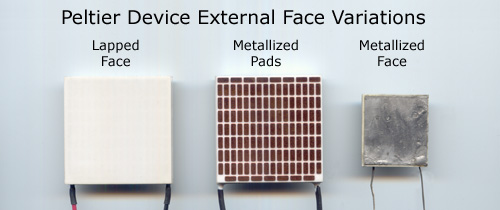
Lapped or Metallized?
Just a quick observation and comparison to the following pictures is all you need to determine the face condition. Rarely, you may find a TE module that is metallized on one face and lapped on the other.
Couples:
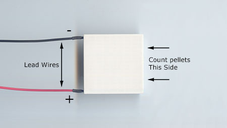
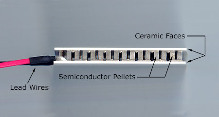
If you look at the sides of a (unsealed) thermoelectric device, you will see lots of “columns” of a dark silvery grey material with space in between. Each individual column is a pellet. [See Side view picture] These thermoelectric pellets do the actual heat pumping work of a TE device. A thermoelectric device contains both N and P doped semiconductor pellets arranged in pairs called Couples, so basically there are twice as many pellets as there are couples. For example, a single 127 couple TEC will actually contain 254 pellets (127 N and 127 P). Each of these pellets will have two solder connections making for a total of 508 solder joints!
Look at the side of the Peltier opposite the side with the lead wires. (See above image) Count the number of pellets that you see. It is usually an even number.
Use the following formula: Couples = [ (Count2)/2]-1
For example, you count 12 pellets, therefore [122/2]-1 = 71 couples
Table of common values
Count Couples in TEC 4 7 6 17 8 31 10 49 12 71 14 97 16 127 18 161 20 199 22 241 24 287
If you have a rectangular device, count the pellets on the side of the Peltier opposite the side with the lead wires (as before) and count the pellets on an adjacent side. If there is a pellet missing due to the lead wire, count it as if it WERE there.
Use the following formula: Couples = [ (Count1 x Count2)/2]-1
For example, you count 12 pellets and 6 pellets, therefore [(12 x 6)/2]-1 = 35 couples
The top two most common couple configurations are 127 and 71. Other common configurations are 7, 17, 23, 31, 35, 47, 63, 71, 95, 127, 161, 199, 241, and 287. Note that 99% of all TECs have odd couple counts.
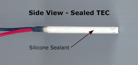
If your Thermoelectric module has a sealant around the edges that prevents you from counting the pellets then there are two options. [What is sealant? click here]
Option 1: Send the device to us for analysis.
We can remove the sealant and perform the analysis using our specialized test equipment. Please see the address at the beginning of this page.
Option 2: Remove the sealant yourself.
If the sealant is “rubbery” and elastic it is more than likely a silicone based sealant. If you are very careful, use a razor blade or X-acto knife to carefully cut away at the silicone on one side. You will slowly reveal the soft silvery pellets underneath enough to be able to count them. Another alternative is to use a silicone remover. Products such as Moreau Marketing’s (www.rmoreau.com) SU100, or RPM Technolgy’s (www.rpm-technology.com) Digesil NC and Digesil NCX, or Dynaloy’s (www.dynaloy.com) Dynasolve 220 will work by immersing the TE module into a glass of the liquid remover and waiting several hours. Many of these removers will work quicker if the solution is heated to around 120ºF. Brush off any excess and rinse in warm water. Follow the specific product directions.
If the sealant is hard or rigid it is likely an epoxy or acrylic based sealant. Immerse the device in a glass of liquid paint stripper containing methylene chloride. [methylene chloride is a hazardous substance and care should be used when handling it] Remove the module from the glass every 30 minutes and brush off any loose pieces of sealant and then return to the glass. Remove and rinse with alcohol when all sealant is loose.
Amperage (Imax):
This is the most difficult specification to determine without specialized equipment.
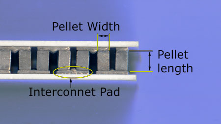
Using a dial caliper, carefully measure the width of 5 or more pellets. Do this under a magnifier or low power microscope if possible so that you can see that you are not crushing the pellets. Find the average of your measurements and make note of it as “W”.
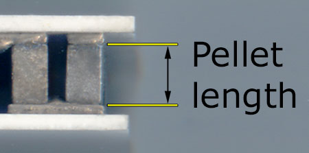
Using the caliper, measure the length of several pellets. Measure only the pellet length and NOT the interconnect pad. See the above image. Again, this is method is more accurate if done under a microscope or magnifier so you can see what you are doing more clearly. Find the average of your measurements and make note of it as “L”.
Now calculate the Length to Area ratio as follows;
Length to Area Ratio = L / W2
Compare your result to the following table to find the closest match.
| Length to Area Ratio Table | ||
| L/W2 (inches) | L/W2 (mm) | Pellet Amperage (Imax) |
| 55.2 | 2.17 | 2 |
| 36.8 | 1.45 | 3 |
| 27.6 | 1.09 | 4 |
| 22.1 | 0.87 | 5 |
| 18.4 | 0.72 | 6 |
| 13.8 | 0.54 | 8 |
| 12.3 | 0.48 | 9 |
| 11.0 | 0.43 | 10 |
| 9.2 | 0.36 | 12 |
| 7.9 | 0.31 | 14 |
| 6.1 | 0.24 | 18 |