Custom Thermoelectric - Peltier

TEC Part # Structure & Option Codes

TEC/TEG PART NUMBER STRUCTURE AND OPTION CODES

Example Part Number: 12711-5L31-03CQ-S

    • First 3 digits are the number of couples (N and P pellet pairs) in the device.
    • 4th digit denotes TEC faces. See "Face Options" below.
    • 5th digit denotes the number of stages or a specialized device

        "1" is single stage device, the most common.
        "2" is a 2 stage device.
        "3" is a 3 stage device.
        "4" is a 4 stage device.
        "5" is a 5 stage device.
        "C" indicates this 1 Stage device is specifically built for Thermal Cycling applications.
        "T" indicates this 2 Stage device is specifically built for Thermal Cycling applications.
        "G" indicates this is a TEG (ThermoElectric Generator).

    • 6th place is a "-" (dash).
    • 7th digit denotes the maximum temperature rating of the TE device.

        "4" is 110°C rated
        "5" is 125°C rated
        "6" is 150°C rated
        "7" is 320°C rated
        "8" is 260°C rated
        "9" is 200°C rated

    • 8th digit denotes lead wire type. See "Wire Types" below.
    • 9th digit denotes height tolerance of module. See "Height Tolerance" below.
    • 10th digit is an amperage multiplier for digits 12 and 13. "1" is 1X, "0" is 0.1X

        "1" is 1X or multiply by 1.
        "0" is 0.1X or multiply by 0.1.

    • 11th place is a "-" (dash).
    • 12th and 13th digits denote the amperage (Imax) of the device
    • 14th digit denotes the series (Company internal reference only) Using B, C, D, and R.
    • 15th digit denotes physical size. Rectangular devices may use two letters such as "FL" = 15x30mm.

        "A" is 8mm
        "B" is 10mm
        "D" is 12mm
        "E" is 13mm
        "F" is 15mm
        "G" is 20mm
        "H" is 22mm
        "J" is 23mm
        "K" is 25mm
        "L" is 30mm
        "M" is 35mm
        "N" is 36mm
        "P" is 38mm
        "Q" is 40mm, the most common size.
        "R" is 44mm
        "T" is 45mm
        "V" is 49mm
        "W" is 50mm
        "X" is 55mm
        "Y" is 59mm
        "Z" is 62mm
        "U" followed by a number denotes mini TECs. "U4" = 4mm.

    • Remaining digits after the 15th digit are used for further options. See below.


    Face Options

    4th digit of part number, default is "1"

      NOTE: Not all face options are available on all products.

      0 = Metallized, top and bottom faces, alumina ceramics
      1 = Lapped, top and bottom faces, alumina ceramics
      P = Lapped, top and bottom faces, "Porch" style w/ bottom face longer in one direction

      The following face options are custom. Please call to discuss.

      2 = Metallized top, lapped bottom, alumina ceramics
      3 = Lapped top, metallized bottom, alumina ceramics

      4 = Metallized, top and bottom faces, alt ceramics
      5 = Lapped, top and bottom faces, alt ceramics
      6 = Metallized top, lapped bottom, alt ceramics
      7 = Lapped top, metallized bottom, alt ceramics

      A = Metallized top in alt ceramic, metallized bottom in alumina ceramic
      B = Lapped top in alt ceramic, lapped bottom in alumina ceramic
      C = Metallized top in alt ceramic, lapped bottom in alumina ceramic
      D = Lapped top in alt ceramic, metallized bottom in alumina ceramic

      E = Metallized top in alumina ceramic, metallized bottom in alt ceramic
      F = Lapped top in alumina ceramic, lapped bottom in alt ceramic
      G = Metallized top in alumina ceramic, lapped bottom in alt ceramic
      H = Lapped top in alumina ceramic, metallized bottom in alt ceramic

      M = No top ceramic, metallized bottom alumina ceramic
      N = No bottom ceramic, metallized top alumina ceramic
      J = No top ceramic, lapped bottom alumina ceramic
      Q = No bottom ceramic, lapped top alumina ceramic
      R = No top ceramic, metallized bottom alt ceramic
      T = No bottom ceramic, metallized top alt ceramic
      V = No top ceramic, lapped bottom alt ceramic
      W = No bottom ceramic, lapped top alt ceramic

      X = No ceramics top or bottom (interconnect tabs only)


      Wire Types

      8th digit of part number, default is "L" for most TECs.

        NOTE: Not all wire options are available on all products.

        U = 32 AWG or less Bus wire
        A = 30 AWG Bus wire
        6 = 29 AWG Bus wire
        B = 28 AWG Bus wire
        3 = 27 AWG Bus wire
        C = 26 AWG Bus wire
        Z = 24 AWG Bus wire
        V = 22 AWG Bus wire
        D = 20 AWG Bus wire
        I = 18 AWG Bus wire
        E = 16 AWG Bus wire

        2 = 32 AWG Bus wire w/ insulation
        F = 30 AWG Bus wire w/ insulation
        7 = 29 AWG Bus wire w/ insulation
        S = 28 AWG Bus wire w/ insulation
        5 = 27 AWG Bus wire w/ insulation
        G = 26 AWG Bus wire w/ insulation
        T = 24 AWG Bus wire w/ insulation
        W = 22 AWG Bus wire w/ insulation
        H = 20 AWG Bus wire w/ insulation
        O = 18 AWG Bus wire w/ insulation
        Y = 16 AWG Bus wire w/ insulation

        4 = 32 AWG stranded wire w/ insulation
        J = 30 AWG stranded wire w/ insulation
        8 = 29 AWG stranded wire w/ insulation
        N = 28 AWG stranded wire w/ insulation
        K = 26 AWG stranded wire w/ insulation
        Q = 24 AWG stranded wire w/ insulation
        R = 22 AWG stranded wire w/ insulation
        L = 20 AWG stranded wire w/ insulation
        P = 18 AWG stranded wire w/ insulation
        M = 16 AWG stranded wire w/ insulation

        X = No lead wires

        WT = PTFE insulation required, code is added to end of part number

        WP = Polarity color of lead wires is reversed. Code is added to end of part number.

        WLxxx = Custom wire lengths, where xxx is length in mm. Two different wire lengths are both indicated as follows WLxxx/xxx. Example: WL150/250 black wire is 150mm, red wire is 250mm. Code is added to end of part number. Also WTLxxx = PTFE insulated wire with custom length.

        Maximum wire length is 460mm (18.1").

        HS = Heat Shrink tubing on lead wires. Code is added to end of part number.

        These wire options are only available on specific TECs.

        W1 = Lead wires exit on same short side of TEC

        W2 = Lead wires exit on diagonal corners of TEC

        W3 = Lead wires exit on same long side of TEC

        Call for quote on custom wire types and lengths

        Standard insulation material for 125°C rated parts is PVC. Teflon (PTFE) insulation is used on 200°C and 300°C rated parts.


      Height Tolerance

      9th digit of part number, default is "3" for most TECs.

        NOTE: Not all height tolerances are available on all products.

        0 = Unmachined/unlapped
        1 = ±0.010" [±0.25mm]
        2 = ±0.007" [±0.18mm]
        3 = ±0.005" [±0.13mm] Default for most TECs.
        4 = ±0.0005" [±0.013mm] (For Titan metallized TECs only)
        5 = ±0.0003" [±0.008mm] (For Titan metallized TECs only)
        6 = ±0.002" [±0.05mm]
        7 = ±0.001" [±0.03mm]
        9 = ±0.004" [±0.10mm]

        Tolerances shown in inches [millimeters].

        • Ask for "Height Matching" when using 2 or more TECs between the same two surfaces. [Height matching is more economical than specifying a tighter height tolerance code for an entire order.] Height matching assures even pressure and heat transfer across the set of TECs.

        • M1 = Height matching to within +/- 0.001"(for multi TEC sets)
          M2 = ACR resistance matching (for multi TEC sets)
          M3 = Height and ACR resistance matching (for multi TEC sets)

        • Typical Height Matching tolerance is +/- 0.001"

        • Choose a height tolerance that suits your application. Codes 4, 5, 6, 7, and 9 are an additional cost.


      Sealing Options

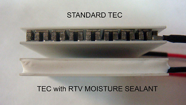
      Codes are added to the end of the part number.

        S = Silicone RTV moisture sealed edge

        SU = Urethane (polyurethane) based edge seal

        The following Epoxy based syntactic foam ruggedization seals the TEC from moisture and debris AND also strengthens the TEC against shock, vibration, and shear forces.

        SE = Epoxy edge seal, 2+ mm deep

        SR = Epoxy Ruggedized Sealing, 5+ mm deep

        SRX = Epoxy Ruggedized Sealing, 5+ mm deep, with epoxy potting to extend around lead wires following width and thickness of TEC

        SRD = Epoxy Ruggedized Sealing, 10+ mm deep or complete fill

        SRDX = Epoxy Ruggedized Sealing, deep to 10+ mm or complete fill with epoxy potting to extend around lead wires following width and thickness of TEC

        Parylene vapor deposition coatings

        SP = Parylene vapor deposition coating

        SPS = Parylene coating with RTV silicone edge seal

        SPU = Parylene coating with Urethane edge seal

        SPE = Parylene coating with Epoxy edge seal, 2+ mm deep

        SPR = Parylene coating with Epoxy Ruggedized sealing, 5+ mm deep

        Sealing protects the internal components from corrosion and electrical "shorts" from moist or wet environments. This includes ordinary environments where you may be taking the cold side of the TEC below the local "dew point" thereby creating condensation and/or ice on the TEC.

        Sealing protects the internal pellets from dirt, dust, and other contaminants that may collect there over time. These contaminants may corrode the pellets or eventually create an electrical "short" therby damaging the TEC. Ask for a sealed TEC if your application is in a particularly dusty environment..

        Sealing has a minimal effect on the TECs capability to pump heat (Q) and its maximum delta T. Typical effects are 1-2% on heat pumping capacity and 1-2 degrees on maximum delta T.


        Sectioning Options

        Codes are added to the end of the part number.

          Not all sectioning codes are available on every TEC. Please call or email for sectioning codes available for a specific TEC.

          C1 = Bottom plate sectioned into 4 pads
          C2 = Bottom plate sectioned into 9 pads
          C3 = Bottom plate sectioned into 16 pads
          C4 = Bottom plate sectioned into 25 pads
          C5 = Bottom plate sectioned into 36 pads
          C6 = Bottom plate sectioned into 49 pads
          C7 = Bottom plate sectioned into 64 pads

          Sectioning of TEC's greater than 25x25mm (1x1") in cycling and extreme duty applications reduces thermal stresses and extends TEC life. Call for more information.


        Additional Options

        Codes are added to the end of the part number.

          Not all codes are available on all TECs. Please call to discuss.

          E1 = Mil spec testing and Burn-in
          E2 = Custom Burn-in

          T1 = Tinned on bottom w/ solder
          T2 = Tinned on top w/ solder
          T3 = Tinned on top & bottom w/ solder

          RP = Reversed polarity of internal pellets

          TTn = Thermocouple or Thermistor mounted to top ceramic where "n" is a station number on the TEC ceramic. Please call for assistance.
          TBn = Thermocouple or Thermistor mounted to bottom ceramic where "n" is a station number on the TEC ceramic. Please call for assistance.

          M1 = Height matching to within +/- 0.001"(for multi TEC sets)
          M2 = ACR resistance matching (for multi TEC sets)
          M3 = Height and ACR resistance matching (for multi TEC sets)

          GT = Graphite TIM pre-applied to Top ceramic face only.
          GB = Graphite TIM pre-applied to Bottom ceramic face only.
          G2 = Graphite TIM pre-applied to Both top and bottom ceramic faces.

          Pnn = Paint/coat ceramic surface, color code, surface to be coated (T = top, B = bottom, 2 = both surfaces)
          Example: PBT = Paint/coat Black on Top surface only