
TEG Installation
Please download our TEG Installation Guide 
Thermoelectric (Seebeck) Power generation modules or TEGs have a large thermal expansion (and contraction) through the range of allowable temperatures -60ºC to 320°C. It is vitally important that the mounting system allow for this expansion and contraction while maintaining an even pressure on the module.
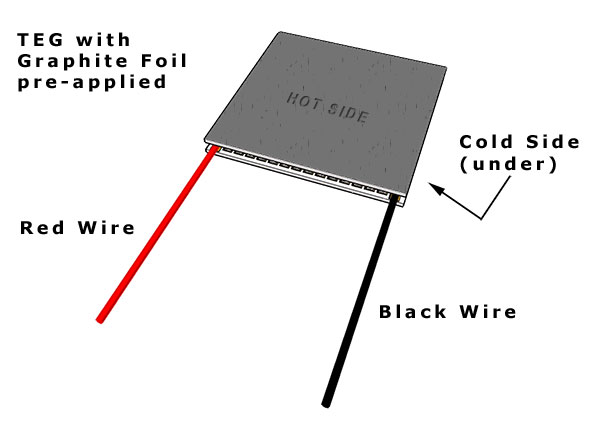
Hot and Cold Side Identification:
Thermoelectric (Seebeck devices or TEGs) generators will only generate electricity if there is a temperature difference across the module. That means that the “cold” side must be at least colder than the “hot” side for there to be any power generation. The hot side is generally attached to a source of heat while the cold side is typically connected to a heat sink that is air or liquid cooled (water block).
NOTE: Keep in mind that the heat from the hot side must travel through the TEG to the cold side in order for there to be electricity generated. It is vitally important that the heat sink on the cold is able to quickly get rid of this heat in order to stay cool. If the cold side cannot get rid of this heat then it will not be the cold side for very long. Use of a Water Block or liquid heat exchanger will significantly increase heat dissipation thereby increasing power generation.
Examine the diagram below. The view is seen as if the module is placed on a table in front of you as shown with the wires pointing towards you.
|
Temperature Limits |
Thermal Interface:
A Microscopic Look at Surfaces Even when you have two “flat and smooth” surfaces, they are far from truly flat or smooth. The diagram below shows what’s really going on at a microscopic scale.
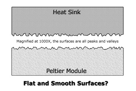
As you can see, the two surfaces may look flat and smooth, but in reality, when examined under magnification, they consist of “hills”, “peaks”, and “valleys”. When these two surfaces are brought into contact with one another, only the peaks make contact. It has been calculated that the average amount of contact between any two smooth surfaces is in reality only 5%. The other 95% are voids!
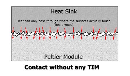
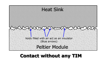
The above image shows how the remaining valleys create voids through which heat energy can barely pass through, in effect creating an insulated area – not the ideal thermal interface.
Surface Finish and Preparation
As a minimum, any surface intended to be part of a thermal interface should be flat to +/- 0.001 inches over the entire interface surface and smooth to a surface finish of 32 micro inches or better.
If possible, a polished surface is better since it ultimately reduces the size and depth of the “peaks” and “valleys”. A polished surface finish of #6 to #8 is good, but the economics of polishing may determine a different stopping point for your product. If polishing is used, make sure to remove all polishing residues – see cleaning below.
The interface surface must be thoroughly cleaned, once all machining and polishing is completed. Ultrasonic cleaning first in a heated degreaser solution and then in a solvent such as acetone is highly recommended to remove all oils and debris. (Never place a TEG or Peltier device in an ultrasonic cleaner!) Do not touch the surface with bare hands (skin oils) or allow any contact with other materials. It is better to complete this final cleaning stage just before assembly so as to minimize any dust or contamination.
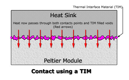
Thermal Interface Materials (TIM)
A Graphite Foil TIM has been pre-applied to both sides of the TEG. (It is dark grey in color) The purpose of this TIM is to fill the valleys and gaps with a compressible material that has a much higher thermal conductivity (ability to transfer heat) than the air gaps it replaces. This essentially makes the entire interface transfer heat instead of just where the peaks were contacting. The following image shows how the situation has been dramatically improved.
Notes about the Graphite Foil TIM
The graphite foil TIM has been pre-applied to both sides of your TEG. Handle the TEG by its edges and try NOT to handle it by touching the graphite foil surfaces. The graphite foil is actually fragile and can easily be damaged. Grooves, scratches, dents in the graphite foil will decrease its ability to conduct heat. DO NOT apply any other TIM (thermal grease or compounds) to the graphite foil. It is ready to use in your power generating assembly.
TEG Mounting:
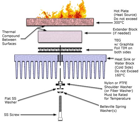
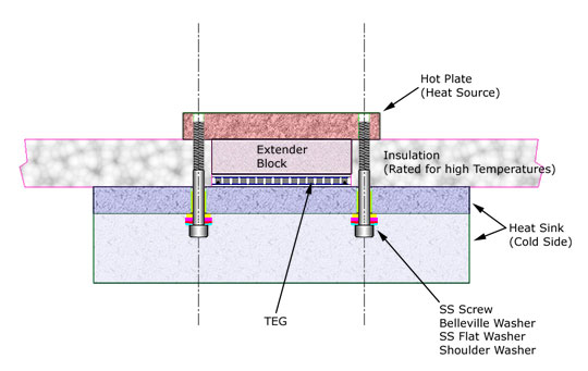
TEGs should be mounted using the compression method. That is, the TEG is compressed between a hot plate and a heat sink (or water block) that will be cooler. The compression or clamping should be created with stainless steel machine screws on either side of the TEG. See Exploded View and Section View images below.
Clamping Forces:
The following table lists the clamping forces required for optimum power generation and thermal contact.
| TEG Size | Pressure | Total force per TEG | Torque per Screw |
|
30 x 30 mm
|
1275 kPa (185 PSI)
|
118 Kg (260 lbs)
|
See Formula Below
|
|
40 x 40 mm
|
1275 kPa (185 PSI)
|
209 Kg (460 lbs)
|
|
|
50 x 50 mm
|
1275 kPa (185 PSI)
|
324 Kg (715 lbs)
|
|
|
56 x 56 mm
|
1275 kPa (185 PSI)
|
408 Kg (900 lbs)
|
Torque per screw can be approximated using the following formula;
Torque per Screw (inch–lbs) = (0.2) X (Screw Diameter) X (Pressure) X (TEG Surface Area)
(Number of Screws)
|
Unified Screw Threads
|
Metric Threads
|
|||
|
Screw Size
|
Screw Diameter
|
Screw Size
|
Screw Diameter
|
|
|
4-40
|
0.112
|
M2.5 x 0.5
|
2.48 (.098”)
|
|
|
6-32
|
0.138
|
M3 x 0.5
|
2.98 (.117”)
|
|
|
8-32
|
0.164
|
M4 x 0.7
|
3.978 (.157”)
|
|
|
8-36
|
0.164
|
M5 x 0.8
|
4.976 (.196”)
|
|
|
10-24
|
0.190
|
M6 x 1.0
|
5.974 (.235”)
|
|
|
10-32
|
0.190
|
|||
Screw Position:
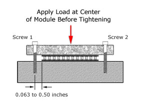
Locate bolt holes in your assembly such that they are at opposite sides of the center of the TEC between 1.0 mm to 12.7 mm (0.04 to 0.5 inches) from the sides of the TEC. [See first image below] The bolt holes should be in the same plane line as the fins to minimize any heat sink bowing (bending) that might occur.
Clamping Procedure:
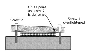
Before tightening the screws, apply a light load/force in line with the center of the TEG by using a clamp or weights. Make sure the clamp or weights apply the force evenly and at the center. Bolt carefully, by applying torque (tightening the screws) in small increments, and alternating between screws. It is of the utmost importance that the screws are tightened evenly in small increments back and forth. If one screw is over tightened, then the tightening of the second screw may crush the TEG. [See 2nd image above] Use a torque limiting screwdriver for best accuracy. Check torque after 1-2 hours and retighten as needed. Repeat this check and tightening procedure again after several hours of actual use.
NOTE:
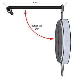
If a torque screwdriver is not available, a reasonably accurate pull spring scale* attached to the end of an L-shaped hex (Allen) wrench (this is a good reason to use socket head cap screws) can be used to determine when the screw torque is reached. Make sure the spring scale is pulled perpendicular (90°) to the Allen (Hex) Wrench at all times.
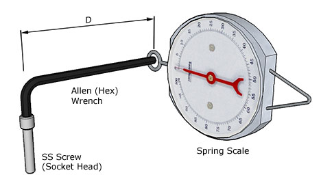
To calculate the required spring scale pull force, use this formula:
F = T / D
F = Force (lbs)
T = Torque (inch-lbs)
D = Distance (inches)
Example: What is the spring scale pull force required at the end of a 3.75 inch long L-shaped hex wrench to produce a 24 in-lbs screw torque setting?
F = 24 in-lbs / 3.75 in = 6.4 lbs pull force
[* Test the accuracy of the pull spring scale by hanging a known weight from the scale and adjust as needed]